An Improved Sine Shaper Circuit
J. Donald Tillman
Apr 11, 2020
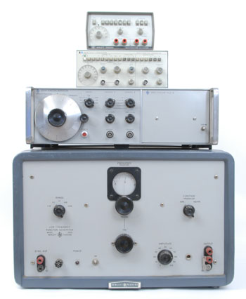
Hewlett-Packard function generators.
(Models HP 202A, 3300A, 3312A, 3311A)
Photo:
HP Memory Project.
In the fields of test equipment and electronic music, the best practice for generating a waveform is a circuit topology where a current source linearly charges a capacitor and switches direction between positive and negative reference voltages. This generates a precision triangle wave. Other waveforms are derived from there by waveshaping with nonlinear circuitry. This approach can be extremely precise, stable, can be voltage-controlled over a wide range, and can offer multiple waveforms simultaneously.
In the test equipment field this is called a Function Generator. Hewlett-Packard has offered function generator models since the HP 202A in 1952 (!!!), with sine, square, and triangle waves. (This is not the same as the orginal HP 200 audio oscillator, which was a tunable Wein Bridge oscillator that only offered a sine wave signal.)
In electronic music this is called a Triangle Core Voltage-Controlled Oscillator or a Sawtooth Core Voltage-Controlled Oscillator. Robert Moog introduced the Moog 901 sawtooth core VCO in 1965, which offered sine, sawtooth, triangle, and pulse/square waves. Donald Buchla introduced triangle core VCOs in the mid 60s. Whether the triangle wave is provided by the core oscillator, or shaped from a sawtooth wave, it gets shaped to make a sine wave output.
Sine-Shaping Approaches
A mathematician will be happy to offer lots of ways to generate a sine approximation. The problem is that most of these are very difficult to implement in analog circuitry. Good luck trying to imlement a Taylor Series with op amps.
A sine shaper is a nonlinear circuit that shapes a triangle wave into a sine wave. Both Tim Stinchcombe's “Triangle Wave to Sine Wave Conversion” and Open Music Labs' “Optimization of an OTA Based Sine Waveshaper”, in the references below, provide excellent overviews.
HP function generators have used a piecewise linear approximation circuit. It involves a set of diodes where each diode starts conducting as the input voltage increases, chipping down the peaks of the triangle wave. This approach can be, not surprisingly, a little bumpy. If you put the sine wave through a high pass filter or differentiator, the transitions are generally visible.
Buchla used a circuit that emplys a Junction Field Effect Transistor with two diodes to change the resistance with input level. The circuit is not known for accuracy, and as JFET manufacturing is wildly inconsistent, the circuit requires trimming.
The most popular approach is an overdriven differential amp implemented with a pair of bipolar transistors. Some call this a "long tail pair". Let's dive into this a little more.
Differential Pair Amplifier
Bipolar transistors have an accurate exponential relationship between the base voltage and the collector current. And two matched transistors in a differential amp configuration have an accurate tanh transfer function:
$$I_o = I_S \tanh(\frac{V_i}{2kT/q})$$
Where \(I_o\) is the differential output current, \(V_i\) is the differential input voltage, \(I_S\) is the transistor's saturation current, K is Boltzman's Constant, T is the temperature in degrees Kelvin, q is the charge on an electron. Typically \(kT/q\) works out to 26mV.
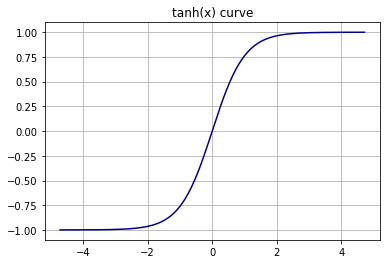
The hyperbolic tangent function is equivalent to:
$$ \tanh x = \frac{e^x - e^{-x}}{e^x + e^{-x}} $$
And looks like this:
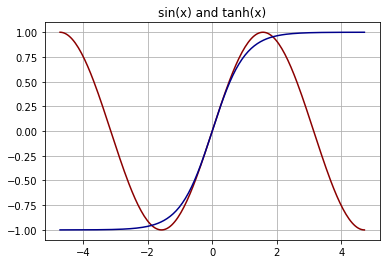
Comparing the tanh function to the sin function suggests its use as sine shaper.
So the idea is that, by driving the differential pair beyond their linear range, we can round the triangle wave into something that resembles a sine wave. This turns out to be a very rough approximation. Here is the tanh curve with various amounts of triangle drive level:
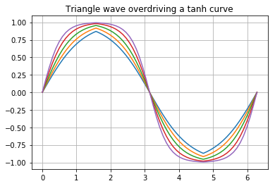
We can see that lower levels leave the wavefrom pointy, and higher levels leave the waveform misshaped. There isn't really a respectable sine wave to be found here. The best case has the harmonics down a little less than 40dB.
So the next step is to alter the shape of the tanh curve by applying some feedback, usually in the form of emitter resistors and adjusting the drive level. Here are some feedback curves with the real sin curve in red:
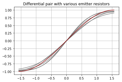
Emitter resistors can bring the harmonic content down an additional 10dB, to -50dB, in the most optimized case.
Another problem is that, unless the shaper curve is exactly horizontal at the +/−90 degree points, the cusps of the triangle wave will get through. Some sine shaper implementations include cusp cancellation, where a little of the initial triangle wave is subtracted from the differential pair output signal to cancel out these cusps.
But what if we go beyond cancelling out the cusps...
An Improved Sine Approximation
Consider taking the tanh function, and subtracting some coefficient β times x from it. Spoiler alert; a β value of 0.710 turns out the work best. Not surprisingly this creates a tanh function that slants down, with a little wiggle in the middle where it slants up:
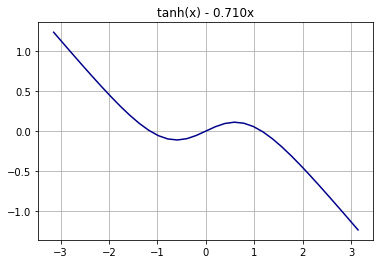
The β value of 0.710 value was carefully chosen so that the section of the curve between the negative and positive peaks approximates a sine function most accurately.
Scaling this equation along the x-axis to 2π radians, and then scaling it along the y-axis to grow it to +/− 1.0, provides a very accurate sine approximation. To differentiate it from a proper sin function I am calling it a tsin function.
$$ \DeclareMathOperator\tsin{tsin} \tsin (x) = 9 \tanh (0.3833 x) - 2.449 x $$
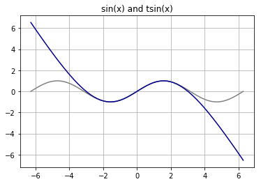
There is a sin() function in gray behind it for comparison.
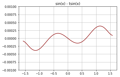
This approximation is remarkably accurate. Here is a plot of the error, the difference between a proper sin function and the tsin function, between the x values of −π and +π. The y-axis scale has been expanded.
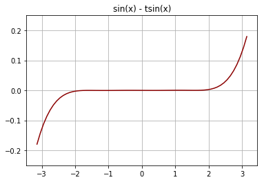
And we only intend to use this between two quarter cycles, between between −π/2 and +π/2. So zooming in on that area we can see that the error is less than 0.00028, or within 0.028%.
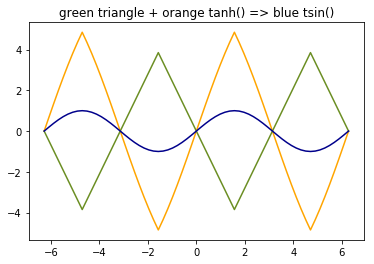
We can break the tsin wave down into the two components to see what is happening. The triangle contribution is almost as great as the tanh. And the differential amp pair has much less waveshaping to do; instead of shaping a sine wave directly, it now has to perform a more subtle operation, one that is much better suited to its natural tanh curve.
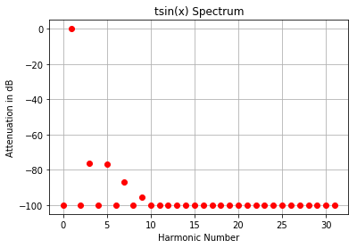
The frequency spectrum of the tsin() function is shown here. 75dB or more below the fundamental, mostly 3rd and 5th harmonics.
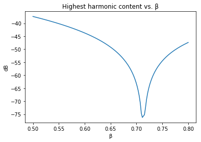
The value of β can be anywhere between 0 and 1, but in practice it's not helpful below .5, it's best at 0.710, and gets worse above that.
Derivation
The x value for the peak is determined where the derivative is zero:
$$ \frac{d}{dx} \tanh(x) - \beta x = 1 - \tanh^2(x) - \beta $$ $$ x_{peak} = \tanh^{-1} (\sqrt {1 - \beta}) $$
Scale x so that the peak corresponds to π / 2.
$$ x_{scale} = \frac{x_{peak}}{\pi / 2} $$
Find the y value at the x peak, and scale whole equation.
$$ y_{peak} = \tanh(x_{peak}) - \beta x_{peak} $$ $$ y_{scale} = \frac{1}{y_{peak}} $$ $$ y = y_{scale}(\tanh(x_{scale} x) - x_{xcale} \beta x) $$
And this is what I used to derive the numbers above.
Implementation Example
The tsin-based sine shaper circuit is similar to a standard differential pair sine shaper... with all the values being wildly different. This example is meant to be more illustrative than optimal for a particular case.
Here we are designing to a +/−1.0 V triangle wave input, and a +/− 1.0V sine wave output. And we've chosen an optimimal β value of 0.710. And we will be running the differential pair from a 1mA current source.
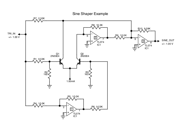
For this precision we need to drive the diff amp pair with a balanced signal. The first op amp provides an inverted version of the input. The second op amp functions as a current mirror. And the third op amp sums the three signals and provides the right gain. R4 = R5, and R8 = R9, but their values are not important, so we're using a generic value of 10.0 K ohm. The 1mA current source is assumed to be available.
The transistors are being operated with 0V between the base and collector. This removes any collector voltage dependencies. The transistors must be matched, of course. R1=R6, R2=R3.Xscale from above, is 0.6021. Yscale, as before, is 9.
The final opamp feedback resistor, R10, is chosen to map the tanh limit, which is the emitter current source, to Yscale. The closest EIA value is 9.09 K ohms.
The input divider resistors are chosen to divide by:
$$ atten = \frac{1}{0.026 X_{scale}} $$
Finally we need a gain of Xscale * β, or -0.6021 * 0.710, relative to Yscale, for the triangle wave.
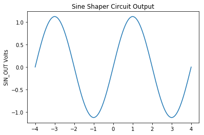
Simulated with those values, the output looks like this:
And the spectrum looks like this:
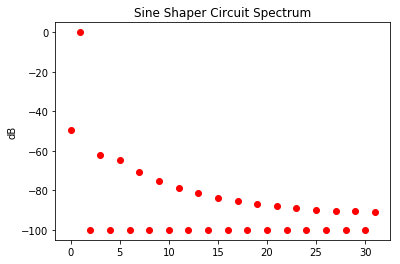
So that's a solid 60dB below the fundamental. I know I can get it lower with non-EIA resistor values. And with some tweaking and trimming you could probably get it down to 70 or 75 dB below the fundamental.
Practical Issues
I have not built this yet, so I don't have hard experience with it. There are a lot of tweaks than can be still be done. I imagine it might be best to back off on the β value, and instead add some emitter resistance. That's an area to be explored.
One question is how this does this sine shaper compare with others under typical component tolerances. So far, under simulation, it seems to have the advantage of fewer upper harmonics. But we'll have to see.
This research for this paper was done over a few days in Jupyter Notebook, with PySpice, Numpy, PyPlot, and a couple pages of Python code.
References
Tim Stinchcombe: Triangle wave to sine wave conversion
Open Music Labs: Optimization of an OTA Based Sine Waveshaper
Robert Meyer, Willy Sansen, Sik Lui, Stefan Peeters: The Differential Pair as a Triangle-Sine Wave Converter, IEEE Journal of Solid State Circuits, June 1976
Texas Instruments: AN-263 Sine Wave Generation Techniques
E. Harry Heflin, Compact Function Generator with Enhanced Capability/Cost Ratio , Hewlett-Packard Journal, July 1973
Robert L. Dudley, A Voltage-Programmable Low-Frequency Function Generator with Plug-In Versatility , Hewlett-Packard Journal, November 1965
HP 202A Low Frequency Function Generator Operating and Service Manual
Robert A. Moog: Voltage-Controlled Electronic Music Modules, Audio Engineering Society
R. D. Middlebrook, I. Richer: Nonreactive Filter Converts Triangular Waves to Sines, Electronics, March 1965
RCA Linear Integrated Circuits, 1970.