till.com Electronic Music Articles

Arp Patents

J. Donald Tillman
September 1999, updated September 2007

Don looks up all the patents associated with ARP Instruments, Inc., and writes up some hopefully entertaining commentary.

I think it is interesting how the guts of some great synthesizer circuitry is described so well in patents yet not covered in books or articles to any great extent.  Sure, patents are the way to protect this sort of intellectual property in a business with some competition, but these patents speak volumes about the approaches the engineers were taking in creating some breakthrough musical instruments.

At the very least the patents, as well as Moog and other synthesizer patents, supply remarkable lessons in not only how to design analog circuitry, but also in how to build a great musical instrument.

The patents here are assigned to Nexus Research Laboratory, a company Alan R. Pearlman (the A.R.P. in ARP) cofounded which made analog modules and opamps, Teledyne, Inc., which purchased Nexus, Tonus, Inc., ARP's original name and ARP Instruments, Inc.

I believe this is all the patents.  If I'm missing any, please let me know.

ARP Patents Reviewed

The Patents

[patent thumbnail]
US Patent 3,230,468:
Apparatus for Compensating a Transistor for Thermal Variations in its Operating Point

Alan R. Pearlman
Nexus Research Laboratory, Inc
Filed: 24 December 1962 (He filed it Christmas eve?)
Issued: 18 January 1966

The first in Alan Pearlman's series of log and exponential converter circuit patents for Nexus Research Laboratory (later Teledyne), this describes a method of compensating for transistor thermal effects with a second matched transistor.  The second transistor is running at a prescribed current, and its base voltage is used to set the operating point of the main transistor.  This will compensate for thermal variations in emitter-base voltage (VBE) and, indirectly, other characteristics. 

Examples are shown for a common emitter case and a similiar common collector case.  Also shown is a differential amplifier stage where the input bias current is compensated for temperature in a similiar way.

[patent thumbnail]
US Patent 3,320,530:
Quasi-Logarithmic Multimeter for Providing an Output which is a Linear Function of the Logarithmic of the Input

Alan R. Pearlman
Nexus Research Laboratory, Inc
Filed: 8 July 1964
Issued: 16 May 1967

If you've ever used an (analog) VOM (Volt Ohm Meter) or a VTVM (Vacuum Tube Volt Meter) to measure resistance, you've probably noticed that the ohms scale is all cramped closely at one end.  This is because these meters measure resistance by applying a known voltage and measuring the resulting current flow.  Ohm's law tells us that the resistance is inversely propotional to the current, so the meter dial is calibrated with a 1/x scale.

This patent is a practical use for the Logarithmic Function Generator (patent described below; it was filed before this one) where the meter displacement is proportional to the log of the ratio between the currents in the measured resistance and a reference resistor.  The meter face is calibrated in a log scale and much easier to use.

[patent thumbnail]
US Patent 3,329,836:
Temperature Compensated Logarithmic Amplifier

Alan R. Pearlman, William D. Miller
Nexus Research Laboratory, Inc
Filed: 2 June 1965
Issued: 4 July 1967

It's a log amp built with a transistor in the feedback loop of an opamp, but there's a second transistor to provide first-order temperature compensation, and a temperature sensitive resistor to provide second-order temperature compensation.  The feedback part of this circuit is very similar to the exponential converter used on most ARP VCOs and VCFs.

A bipolar version of the circuit is also shown.

[patent thumbnail]
US Patent 3,369,128:
Logarithmic Function Generator

Alan R. Pearlman
Nexus Research Laboratory, Inc
Filed: 10 February 1964
Issued: 13 February 1968

"A device for determining the logarithm of the ratio of two signals".  Use a transistor as a log amp, you'll need a second transistor to compensate for the temperature sensitivity, that requires subtracting the two signals, and subtracting two logs is the same as the log of a ratio, so you might as well build it all into one functional block.

[patent thumbnail]
US Patent 3,444,362:
Antilogarithmic Function Generator

Alan R. Pearlman
Teledyne, Inc.
Filed: 30 October 1964
Issued: 13 May 1969

An exponential converter using two transistors where one transistor performs the linear-voltage-to-exponential-current function and a second transistor runs at a constant current and provides a temperature-tracking offset.  Diodes can be used instead of transistors with a slightly different circuit.

Only first-order temperature compensation is covered here.

[patent thumbnail]
US Patent 3,665,089:
Music Synthesizer Keyboard

Richard Stearns
Tonus, Inc.
Filed: 17 December 1970
Issued: 23 May 1972

This is the patent for the two-voice ARP keyboards for the ARP 2500 and the 3620 keyboard for the ARP 2600.  A very similiar circuit is used in the ARP Odyssey and the Moog 952 two-note keyboard for the Moog Modular.

Typical synthesizer keyboards are built with a string of resistors driven by a constant current source at the high end and grounded at the low end.  A bus of keyswitches taps a voltage off the resistor string.  When the player hits more than one key the output voltage defers to the lowest note played.

In this patent it is noted that the voltage at the top of the resistor string is related to the span of notes held down, and a little differencing circuit calculates the highest note voltage from the lowest note voltage and the span.

References:
  • ARP Synthesizer Series 2500 Owner's Manual, ARP Instruments, Inc., 1971, 2nd edition September 1974
  • ARP 3620 Keyboard Service Manual, ARP Instruments, Inc., 1977
  • ARP Odyssey Service Manual, ARP Instruments, Inc.
  • Technical Service Manual for the Moog Modular System, Norlin Music
[patent thumbnail]
US Patent 3,715,444:
Switching System for Keyboard

Alan R. Perlman
Tonus, Inc.
Filed: 4 January 1971
Issued: 6 February 1973

This is a low-tech method of using a keyboard to drive a polyphonic synthesizer.  It provides a note-prioirty system where the played notes route to the VCO's in the note order, either low-note priority or high-note priority.  The clever thing is that it does this with pre-microprocessor technology; it's all in the wiring of the keyboard switches.

For an N-note polyphonic synthesizer, where N might be some value between 4 and 8, there is an N-pole-double-throw switch under each key on the keyboard.  When a key is up, the N-poles are just passed to the next key.  When a key is pressed, the N-poles are shifted over one and that key's control voltage is placed on the first pole.

Unfortunately it's not really practical.  Sure, Hammond tonewheel organs have always been built with 9-pole switches under each key, so it's certainly tempting to just grab a keyboard from a junked Hammond.  But a Hammond keyboard is single throw, not double throw, and a Hammond keyboard has a bus structure which wouldn't be adaptable for this.  The keyboard for this system would be mechanically complex and expensive.

There's no "hold" capability, so you won't be able to sustain a note after the keys are released.  And releasing the highest priority note will cause all the others to slide unnaturally.  And any contact imperfections would show up as serious pitch errors.  Still, it might be useful as an improvement on the ARP duophonic keyboard.

[patent thumbnail]
US Patent 3,784,935:
Touch Sensitive Polyphonic Musical Instrument

Alan R. Pearlman, Dennis Colin
ARP Instruments, Inc.
Filed: 15 June 1972
Issued: 8 January 1974

US Patent 4,044,642:
Touch Sensitive Polyphonic Musical Instrument

Alan R. Pearlman, Dennis Colin
ARP Instruments, Inc.
Filed: 29 October 1974
Issued: August 1977

These are really the same patent, I think the latter supercedes the former.  The nineteen figures are identical in both, but the patents have different sets of claims.

A compressible resistive material can be placed under the keys of a keyboard to give you "aftertouch" control (see US 3,965,789 below) except here there is a stack of four pieces of resistive material for each key and connections between them go to capacitors to ground, forming a pressure-sensitive four-pole RC filter for each key.

I do not believe this was ever used in an ARP product.

[patent thumbnail]
US Patent 3,805,091:
Frequency Sensitive Circuit Employing Variable Transconductance Circuit

Dennis Colin
ARP Instruments, Inc.
Filed: 15 June 1972
Issued: 16 April 1974

[patent thumbnail]
US Patent 3,924,199:
N-pole Filter Circuit Having Cascaded Filter Sections

Alan R. Pearlman
ARP Instruments, Inc.
Filed: 4 February 1974
Issued: 2 December 1975

[patent thumbnail]
US Patent 4,011,466:
Dynamic Filter

Alan R. Pearlman, C. Gillette
ARP Instruments, Inc.
Filed: 10 May 1976
Issued: 8 March 1977

It's the ARP filters!  The first patent is for a single-pole voltage controlled low-pass filter using a transconductance amplifier followed by an integrator.  High-pass and all-pass variations are also shown.  (The David Rossum / Oberheim patent US 3,969,682 is nearly identical to this one.)  The ARP 4023 Voltage Controlled Filter module is a two-pole biquad filter using a pair of these circuits as integrators.

The second patent shows how four of the above single-pole filters of the first patent can be connected together with a feedback path to form a four-pole filter with resonance, similar to the Moog ladder filter but without the actual laddder.  Compare it to the SSM 2040 4-pole VCF chip.  Or for that matter, to the CEM 3320 and CEM 3328 4-pole VCF chips.

And the third patent shows how the four-pole filter can be implemented with an LM3900 Norton amplifier.   This is the design for the ARP 4072 and 4075 Voltage Controlled Filter modules which were used on a number of ARP synthesizer models.

References:
  • ARP 4023, 4072, 4075 Voltage Controlled Filter Schematics
  • SSM 2040 Data Sheet, Solid State Micro Technology for Music.
  • CEM 3320 Data Sheet and CEM 3328 Data Sheet, Curtis Electromusic Specialties
  • Musical Applications of Microprocessors, Hal Chamberlin
[patent thumbnail]
US Patent 3,828,110:
Control Circuitry for Electronic Musical Instrument

Dennis Colin
ARP Instruments, Inc.
Filed: 11 July 1973
Issued: 6 August 1974

[patent thumbnail]
US Patent 4,136,595:
Single Bus Keyboard

Timothy Gillette
ARP Instruments, Inc.
Filed: 19 October 1976
Issued: 30 January 1979

Early ARP models used 3-bus keyboards to supply control voltage, gate and trigger signals.  Later ARP models (such as the Odyssey II's and the 3620 2-note keyboards for the ARP 2600) used 2-bus keyboards supplying the control voltage and gate signals with the trigger signal being derived from the gate.

These patents describe reduced-cost 1-bus keyboards.  I don't think the patents were actually incorporated into an ARP product.

I suppose the multiple busses were not a big expense when synthesizers first appeared as they simply used organ keyboards and organ keyboards often had several busses.  The classic Hammond organ models were 9-bus keyboards (not that anybody ever used Hammond keyboards for synthesizers).

In the first patent both the gate and trigger signals are derived from changes in the control voltage, while in the second an oscillator senses the impedance change in the main bus when a key is depressed.

In contrast, the Moog keyboards never separated the gate and trigger functions, they only had a gate signal that they, ironically, called "trigger".  The first Moog keyboard, model 950, was a 3-bus unit supplying control voltage, gate (called trigger) and an extra set of contacts available for free experimentation through a rear connector (!!!).  The model Moog 951 and MiniMoog keyboards were 2-bus units supplying control voltage and gate (called trigger).  And the model Moog 952 two-note and the MicroMoog keyboards were 1-bus units that placed a small high frequency signal on top of the control voltage so that some extra circuitry could detect it and generate the gate signal.

References:
  • ARP 2600 Service Manual, ARP Instruments, Inc., September 1977
  • ARP 3620 Keyboard Service Manual, ARP Instruments, Inc., 1977
  • Technical Service Manual for the Moog Modular System, Norlin Music
[patent thumbnail]
US Patent 3,930,429:
Digital Music Synthesizer

Jeremy Hill
ARP Instruments, Inc.
Filed: 26 April 1974
Issued: 6 January 1976


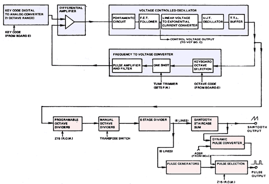
This is most of the circuitry of the ARP Soloist and Pro DGX synthesizers.

Later... (I had originally written "Some day I'll figure out how that VCO works.")

The VCO here is very difficult to understand because it's an unusual circuit and both the patent and the service manual circuit descriptions are misleading.  The goal was to have a VCO run from a digital keyboard input, with digital control over octave tuning from presets stored in ROM, and be inexpensive and accurate.  There is a tendancy to want to implement such a beast as an exponential control over one octave, and then use a flip flop divider chain to extend the range to many octaves, but that wouldn't handle large amounts of vibrato or portamento over multiple octaves.  So this circuit is an alternative to that approach; exponential control over one octave, but octave selection is implemented in a servo loop.

Pro Soloist VCO diagram

The keyboard note value is a 6 bit number, four bits for the note of the scale and two bits for the octave.  There's a DAC for the keyboard note-of-the-scale bits, a nonprecision high frequency VCO, an octave divide chain, a Frequency to Voltage Converter, and a feedback correction circuit.  The confusion comes about because it's not clear whether the DAC, the VCO or the FVC are exponential or linear, and it's not clear where the exponential conversion is actually happening.

The DAC is a rough and tumble affair (TTL gates, a bunch of precision resistors and an opamp summer) implementing 12 notes worth of an exponential curve, and that gets repeated over each octave on the keyboard.  The octave selection actually happens in the servo feedback loop; a tap is made off the VCO output or one of three divide chain flops, and this goes through a simple monostable-and-RC-filter linear FVC, and that gets compared to the DAC output and the difference adjusts the high-frequency VCO.

The essence of this is that both the exponential DAC and the FVC only have to be accurate over one octave.  The high frequency VCO gets divided down a lot later for octave selection and for generating a faux sawtooth by summing octave square waves.

The DAC is exponential, the VCO is exponential, the FVC is linear.  And you take the difference between an exponential control voltage and a linear feedback voltage and drive an exponential high frequency VCO, and it works?  Crazy stuff.

References:
  • ARP Pro Soloist Model 2701 and Pro/DGX Model 2720 Service Manual, ARP Instruments, Inc.
[patent thumbnail]
US Patent 3,965,789:
Electronic Musical Instrument Effects Control

Alan R. Pearlman
ARP Instruments, Inc.
Filed: 1 February 1974
Issued: 29 June 1976

This is the aftertouch feature on the ARP Soloist and Pro/DGX.  It's a strip of compressible resistive material spanning a keyboard.  The construction includes a gap for a "dead band" to separate the touch control from normal playing.  Controls are included to independantly set the touch sensitivity of pitch bend, vibrato and VCF tuning.

References:
  • ARP Pro Soloist Model 2701 and Pro/DGX Model 2720 Service Manual, ARP Instruments, Inc., March 1976
[patent thumbnail]
US Patent 4,144,790:
Choral Generator

Michael Suchoff
ARP Instruments, Inc.
Filed: 14 February 1977
Issued: 20 March 1979

This is the chorus generator used in the ARP Omni and ARP Omni 2 to take a basic organ sound (with an attack and decay envelope) and make it emulate a string orchestra.  The input signal is applied to three BBD delay lines in parallel, each modulated by an independent triangle wave LFO.  The BBD delay lines are clocked with exponential VCOs, so their delay tuning is smooth.

There is one difference between this patent and the actual products; this patent mixes the original signal with the three delayed signals while the Omni and Omni 2 leave out the original in the final mix.  I wonder what the differences are between them?

I've always thought that this chorus circuit would make an excellent rack-mount effects device on by itself.

The patent also suggests setting up four seperate amplifiers and speakers for the three delayed signals and the original.  Gosh, that's gotta sound great with a 12-string electric guitar.

References:
  • ARP OMNI Model 2480 Service Manual, ARP Instruments, Inc., February 1977
  • ARP OMNI-2 Service Manual, ARP Instruments, Inc, July 1978
[patent thumbnail]
US Patent 4,217,803:
Piano-action keyboard

Philip Dodds
ARP Instruments, Inc.
Filed: 2 January 1979
Issued: 19 August 1980

US Patent 4,273,017:
Piano Action Keyboard with Roller and Elastic Diaphragm Transducer

Philip Dodds, Mark Smith
ARP Instruments, Inc.
Filed: 27 February 1979
Issued: 16 June 1981

These two patents go together to describe different aspects of a piano-like keyboard.  This seems to be the mechanism used for the keyboard in the ARP Electronic Piano.

References:
  • ARP 16 Voice Electronic Piano Service Manual, ARP Instruments, Inc., January 1980
[patent thumbnail]
US Patent 4,257,305:
Pressure Sensitive Controller for Electronic Musical Instruments

David Friend, Royce Kahler, Jr.
ARP Instruments, Inc.
Filed: 23 December 1977
Issued: 24 March 1981

This is the PPC (Proportional Position Controller) used on later models of the ARP Odyssey for controlling pitch bend and vibrato.  The pads are sensitive to both pressure and position and make great alternative controllers.

References:
  • ARP Odyssey Service Manual, ARP Instruments, Inc.
[patent thumbnail]
US Patent 3,851,265:
Tone Generating System

Leroy Daniel Young, Jr.
Filed: 5 February, 1973
Issued: 26 November, 1974

(New addition.)

The ARP Avatar was one of the first commercially available guitar synthesizers.  It consisted of a hex pickup that mounted on a standard electric guitar near the bridge, a complex pitch extractor circuit, some additional circuitry, and what is basically an ARP Odyssey synthesizer without the keyboard or keyboard electronics.

There is a lot of mystery surrounding the Avatar; for one thing it was not a popular product and few of them were manufactured.  (I've never seen or played one myself.)  The core of the pitch extractor is the new, interesting and innovative part of the Avatar, and that circuit was potted and schematics were not made available.  At the same time there was some politics and infighting going on inside ARP, and it's been claimed that the Avatar project led to ARP's downfall.

This basic operation of the pitch extractor was patented by Leroy Young a few years before he started working as a consultant with ARP.  The goal is to detect the pitch of a guitar-like input, provide an oscillator output that tracks the input, either at pitch, proportional to the pitch, or with the help of an optional ROM lookup, at an arbitrary relationship to the input pitch.  Either way, the oscillator output can continue after the input signal has faded out.

It's done old-school digitally -- a clocked counter measures the period of each cycle, that value is stored in a register, and the register value is then used to preset a divide-by-N counter from a second clock, and that's your oscillator output.  The ratio of the counter clocks determines the ratio of the output pitch to input pitch.  A note detector senses when the input note has faded out, and that's used to disable updating the period register, so the oscillator output can continue after the guitar note has decayed.

Just to add to the mystery surrounding the Avator, this patent is a little weird and confusing.  The title is deceptive, the section titled Description of Prior Art doesn't actually describe any prior art, the New Note Detector (26) isn't shown at all, neither is the Enable and Clear Gen (28), Figure's 2 and 3 are a gratuitiously complex implementation of a regular schmitt trigger, the blocks in Figure 1 have completely nebulous names ("decoders", "subtract"), none of the inputs or outputs of those blocks are labeled, single wires and buses are drawn exactly the same way, and so forth.

References:
  • ARP Avatar Service Manual, ARP Instruments, Inc., January 1978
[patent thumbnail]
US Patent 4,300,431:
Pitch Extractor Circuit

Paul DeRocco
Filed: 14 December, 1979
Issued: 17 November, 1981

The second mysterious ARP Avatar patent.  Why is ARP not the assignee?  Maybe to hide the patent from competitors?  (It was sure hidden from me until "Mike I" clued me in!)  The content of Leroy Young's patent, above, is included within this patent, yet there's no credit mentioned.  One can only imagine the drama at the time.

The Avatar was a monophonic synthesizer, but it used a hex pickup to provide signals from the individual guitar strings and the hex circuitry in the pitch extractor allowed for a more precise analysis of the signal for the case where the guitarist plays a string while the previous note on a different string is still decaying.  From the hex pickup, the signals for each string go through a preamp and a trigger generator circuit that finds note transients.  From the trigger signals, a priority encoder chip and a latch find the most recently played string, and a multiplexer selects only that string's signal to go through the rest of the pitch detection circuitry.

This patent assumes a hex pickup providing signals for the individual guitar strings, though the pickup itself is not included.  The Roland guitar synthesizer patent (US 4,357,852) was filed 5 months after this one and it does include the hex pickup.

The signal is compressed (to adapt to various playing styles), and filtered (to remove content outside the range we're interested in) and turned into a square wave with some level detectors.  There is some timing circuitry to assure that a full cycle has been found before the pitch conversion process really starts.

Leroy Young's circuit is used to measure the period of input frequency, store that in a register, and use that to set a divide-by-N counter.

In addition there's a 40-bit-long-12-bit-wide shift register build with a pair of Signetics 2519's.  (Wow, how often do you see something like that!).  The period measurement is applied to the shift register, some logic clocks the shift register at 250 kHz during the first 50 mSec after the note starts, and at 1.0 kHz after that.  That's a delay of 0.16 mS at the beginning of the note while the shift register is being filled up, and 40 mSec delay for the rest of the time.  So as the note dies out we still have a sample of the period from 40 mSec before.  This is intended to keep the pitch from sagging as the input waveform decays.

Finally, a phase-locked loop (PLL) tracks the frequency and provides a voltage output that follows the guitar note.  The PLL described here closely resembles the CD4046 with its edge-triggered phase detector.

This patent mostly matches the schematics in the Avatar Service Manual.  The guitar signal processing circuitry of Figure 1 of the patent and the PLL circuitry of Figure 3 are encapsulated modules in the Avatar and their schematics are not included in the Service Manual.  The Avatar also includes a "hex fuzz" circuit which is not mentioned in the patent.

The patent drawings are a little sloppy; a transistor is missing its emitter arrow, some reference designators are used multiple times, a number of components don't have reference designators, some terminals are left unconnected, one of the diodes in the PLL circuit is backwards.  Some of the opamps in the schematics are really open-collector comparators but that's not mentioned in the text so the circuit and its description make no sense at all.  No parts values are given, but I'm guessing that's just to make it more difficult for any competition.

References:
  • ARP Avatar Service Manual, ARP Instruments, Inc., January 1978