J. Donald Tillman
19 July 2003

This is the first of a set of articles about a new Voltage Controlled
Oscillator (VCO) design for electronic music applications based on a
Quadrature Trapezoid wave oscillator core. Here I want to
discuss the basic design, its goals, and applications.
The VCO core is the heart of the oscillator; the part of the
circuit responsible for determining the frequency of oscillation as
well as the basic capabilities of the unit. The VCO core is
supplemented with input circuitry to interface with the input control
voltages and output circuitry to provide a number of desired
waveforms. So while electronic music VCO's produce many
waveforms, they are almost always implemented as a sawtooth or
triangle wave VCO core with a set of waveshaping circuits to provide
the remaining waveforms.
What is a Quadrature Trapezoid? It's a pair of
trapezoid-shaped waveforms; one is called the Trapezoid Sine
and one is called the Trapezoid Cosine. They're 90
degrees apart so that the horizontal section of one wave corresponds
to the the sloping section of the other. This is what they look
like:
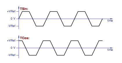
Trapezoid sine and trapezoid cosine waveforms.
|
(I made up the terms Quadrature Trapezoid, Trapezoid Sine and
Trapezoid Cosine. I also abbreviate Trapezoid Sine
as TSin and Trapezoid Cosine as TCos.)
I offer the quadrature trapezoid VCO core as an alternative to
traditional VCO cores for both the audio and low frequency (control
and modulation) ranges.
The quadrature trapezoid VCO has a number of interesting features:
- Quadrature outputs
- Graceful thru-zero FM capability
- Exponential, Scaled Linear, and Offset Linear voltage control
- Audio or low frequency range
- Classic waveforms are easiliy derived from the quadrature
trapezoid waves
- Phase-correct classic audio and LFO waveforms available
- Multicycle voltage controlled phase shift is possible
(I'll be defining what some of those strange phrases mean later in
this article.)
One of the goals of this project is to create a break with tradition
and provide an alternative VCO design with new features and new modes
of operation. The VCO is the primary source for sounds and
modulation sources in electronic music synthesizers, yet it is often
said that the filter is the heart of a synthesizer. This is
because there are more available variations in filter designs and each
filter design has side effects that create an interesting sonic
character. I'll claim that this situation is because VCO designs
are too much alike, have been stuck in a rut for a few decades and
need to jump in a new direction to be more imaginative and musically
useful. So exploring new territory is important.
Thru-zero FM
The original incentive of this project was the challange of building a
VCO that could perform thru-zero Frequency Modulation (FM) -- this is
where a control voltage can tune the oscillator down through 0 Hz to
negative frequencies in a graceful manner. This is a major
component of FM synthesis. While easy to implement in the
digital world, it is a really difficult problem in the analog
domain.
Exactly why would anyone want to tune an oscillator to negative
frequencies?
- FM synthesis
- Chorus effect by FM modulating an LFO with an audio signal
- Rotating speaker and rotational sound source effects
- LFO modulation in general
- Local oscillator for a Bode/Moog style frequency shifter
- Chaotic systems
- Analog computer simulation of rotating objects
Implementing analog thru-zero FM that performs gracefully near 0 Hz is
especially difficult. I'd like to be able to run the VCO near 0
Hz and modulate it both positively and negatively from there, and be
able to do so without any glitches. I couldn't find a way to do
this with traditional VCO cores.
In the digital domain:
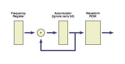
A block diagram of a basic digitally controlled oscillator
(DCO) implmemenation.
|
The standard digital implementation of a VCO incorporates a register
containing the frequency value, an accumulator, and a lookup
table. On each clock pulse the value in the frequency register
is added to the accumulator, the carry bit is thrown away, and the
accumulator value maps to a waveform value with a waveform lookup
ROM. The digital VCO is easily tuned to negative frequencies by
setting the frequency register to a negative (two's complement)
number.
(Now back to analog...)

The classic sawtooth waveform.
|
In an analog sawtooth VCO core, the input control voltage is converted
into a current source that charges the capacitor linearly up to a
reference voltage point, at which the capacitor is quickly discharged.
Taking the sawtooth VCO core to negative frequencies requires ramping
in the opposite direction, sensing a negative reference voltage and
also resetting the capacitor voltage in the other direction. But
after the reverse reset the waveform is at a point where it's ready to
be forward reset again. It's very easy for the wave to get stuck
at one state or oscillate inappropriately between the two resets.

The classic triangle waveform.
|
The triangle wave VCO core is a better candidate for thru-zero
operation because there are no sudden discontinuities. The input
control voltage is (effectively) converted into positive and negative
current sources, the positive current source charges the capacitor
linearly up to a positive reference voltage, at that point the VCO
switches state and the negative current source discharges the
capacitor linearly down to a negative reference voltage where the VCO
switches state back.
But it turns out to be very difficult to take a triangle VCO core
through to negative frequencies. For one thing, the positive and
negative reference voltages could be approached from either the
forward or reverse directions. Hitting the postive reference
voltage no longer implies that we are going forward or that inverting
the current source will switch direction.
If the control voltage goes through zero at the same time the triangle
wave hits a reference voltage then it shouldn't be necessary to switch
current sources at all. If the wrong decision is made when the
triangle wave hits a reference voltage, the triangle voltage could get
lost beyond the reference voltage.
What exactly defines the states? What exactly defines the
transitions between the states? What about the case where we go
to a state boundry and bounce back without actually changing
states? Does the state depend on knowing the polarity of the
input control voltage? If so, how is that affected by real world
offset voltages in either the control circuitry or the capacitor
voltages?
I could not find a way to address these issues with a triangle VCO
core.
Two Dimensions
The fundamental problem is that voltage is a one dimensional quantity,
while waves are continuous and cyclic; they need two dimensions to
physically describe their state accurately.
The digital VCO addresses the two dimensions with a one dimensional
accumulator value that automatically wraps around as a result of
throwing away the carry bit. There's a discontinuity at the
wrap, but there's also a discontinuity on each clock pulse.
The state of a sawtooth core is described by a continuous voltage
plus a momentary reset state. The oscillator is effectively
"off line" during the reset and comes back when the reset is
finished.
The triangle core uses a continuous voltage plus a binary direction
for it's two dimensions. But the points where the binary part
changes state are less clearly defined as the frequency nears 0 Hz.
I decided that I needed two continuous values for my two
dimensions. A sine wave and a cosine wave are an obvious
approach, but maintaining the mathematical relationship between them
near 0 Hz is difficult. And it's difficult to derive other
waveforms from a quadrature pair of sines.
The quadrature trapezoid core has two continuous values for its two
dimensions, like a sine/cosine relationship. And the quadrature
trapezoid is easy to implement -- at any given time one of those
values is changing while the other stays constant.
Implementation
Instead of the traditional single ramping capacitor found in a
sawtooth or triangle VCO core, the quadrature trapezoid VCO core uses
two separate ramping capacitors. The waveform is divided up into
four quadrants. During each quadrant one capacitor is ramping
between a postive reference voltage ("+VRef") and a negative reference
voltage ("-VRef") while the other capacitor is being held at one of
those reference voltages.
Here is a plot showing the quadrature trapezoid waveforms and states:
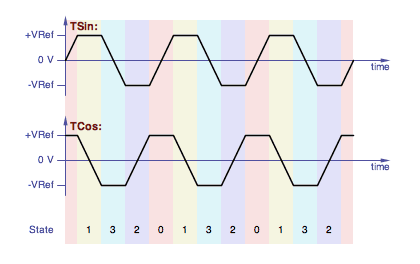
Showing the quadrature trapezoid states.
|
The order of the states is Gray Code, a binary counting system
where only one bit changes at a time. Here we go from binary 00
to 01 to 11 to 10 and back around to 00. Or in reverse.
The state chages when the capacitor that's ramping crosses the
positive or negative value of the capacitor that's being held at a
reference voltage.
Here is the state diagram (the colors match the plot above):
Here the states are all well defined, the transitions between
the states are well defined, and there are no discontinuities when
transitioning between states. Any offset voltages will only
have the effect of altering the specific point where a transition
between adjoining states occurs.
When the states are defined this way, it's very easy to derrive
StateA and StateB, the first and second bits of
the state value, by simply comparing the two capacitor voltages:
StateA is true when TCos < TSin
StateB is true when -TSin < TCos
That's illustrated in this drawing:
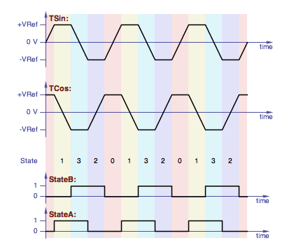
Quadrature trapezoid states with the state waveforms.
|
Here is a block diagram of the quadrature trapezoid VCO core
implementation:
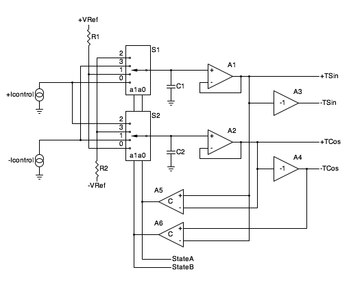
Block diagram of the quadrature trapezoid VCO core.
|
(The second article in this series presents a complete schematic.)
The VCO uses complementary current sources +Icontrol
and -Icontrol to ramp the voltages on capacitors C1
and C2. Each current source is capable of both positive
and negative current flow (sourcing and sinking) and both are
controlled by the input control voltages. The current sources
run "push-pull", so the current of one is equal and opposite the
current of the other.
S1 and S2 are two halves of a dual 4-input analog
multiplexer chip. The multiplexors choose the source for both
capacitors for each quadrant as follows:
|
| State |
to C1 |
to C2 |
| 0 |
+Icontrol |
+VRef |
| 1 |
+VRef |
-Icontrol |
| 3 |
-Icontrol |
-VRef |
| 2 |
-VRef |
+Icontrol |
The dual 4-input analog muliplexer steers four sources into two capacitors.
|
+VRef and -VRef are the reference voltages,
typically +5.0 V and -5.0 V respectively. The reference voltages
define the amplitude of the trapezoid waveforms.
Voltage followers A1 and A2 buffer the capacitor
voltage providing TSin and TCos outputs.
Amplifiers A3 and A4 each have a gain of -1 and
provide the -TSin and -TCos outputs.
A5 and A6 are comparators. These provide
the StateA and StateB signals, defining which
quadrant we're in, and those feed the analog multiplexer.
StateA and StateB are also available
as separate outputs for other purposes (free square waves,
waveshaping, voltage controlled phase shift, etc.).
Waveforms
A trapezoid is probably not the most useful musical waveform there
is. It doesn't have a lot of harmonic content and the harmonic
content it does have contains only odd harmonics. The waveform
also cannot be morphed under voltage control (compared to a square
wave which can have its duty cycle controlled).
However, the quadrature trapezoid is relatively easy to shape into the
classic synthesizer waveforms. And having quadrature phases
available allows waveform conversion techniques that minimize
glitches.
The triangle wave is easiest; simply average the TSin and TCos
waveforms:
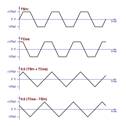
Averaging two quadrature trapezoid waves gives you quadrature
triangle waves.
|
A second triangle wave in quadrature with the first is readily
available by choosing the -TSin wave instead of the TSin. And
the triangles can be converted to sine waves with the classic triangle
to sine shaper circuit.
It's only slightly more difficult to build a sawtooth wave from a
quadrature trapezoid core. One way is to use the StateB line to
switch between two triangle waves:
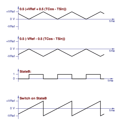
Constructing a sawtooth wave by switching between two triangles.
|
Another feature of the quadrature trapezoid core is that, since
quadrature phases are available, it is possible to have much greater
control over the phase of the generated waveforms.
Phase-correct waveforms are sets of waveforms that are crafted
so that their relative phases are aligned for a particular purpose,
and will be the subject of a later article.
Exponential, Offset Scaled linear and Scaled Linear control
It turns out that the core of a VCO is actually a current controlled
oscillator, because it is a current source that ramps the capacitor
voltage. So the input to a VCO needs to be converted to a
current. And with a thru-zero VCO, that current needs to be able
to swing both positive and negative.
Typically VCO's for musical work are exponential; their
frequency is an exponential function of the input control
voltage. This is the way we hear; the frequencies of an equal
tempered scale are exponential, and the ratio of one note to the next
chromatic note is a constant. To be especially useful, the input
control voltage is typically calibrated to 1.0 Volt/Octave, so
increasing the input control voltage by 1.0 V doubles the frequency
and decreasing the input control voltage by 1.0 V halves the
frequency.
An exponential control voltage by itself cannot tune a VCO to negative
frequencies; as the control voltage goes more negative the frequency
goes toward zero. Thru-zero FM requires linear frequency
control.
When you have both exponential and linear control, there are two ways
the linear control can be implemented; offset linear
and scaled linear. (I made up those terms also.)
In the offset linear case, the linear control is added after the
exponentional control:

Where:
Fvco is the frequency of the VCO in Hertz
Fexp0 is the frequency in Hertz with a 0 V
exponential control voltage
Vexp is the exponential control voltage in Volts
Klin is the linear scaling constant, in Hz/Volts
Voffsetlin is the offset linear control voltage,
in Volts
A typical application of offset linear control would be to detune an
oscillator by a fixed amount for a chorus effect. This would
involve a very low value K
lin constant and the oscillator
would only go to negative frequencies at low values of
V
exp.
In the scaled linear case, the linear control is effectly placed
before the exponential control and therefore scaled or multiplied by
it:

Where:
Vscaledlin is the scaled linear control voltage
in Volts
V
scaledlin might be nominally held at 1.0 V, raised to 2.0
V to double the frequency of the VCO, or lowered to -1.0 V to bring it
down to the mirror-image negative frequency. This arrangement is
much more useful for FM Synthesis.
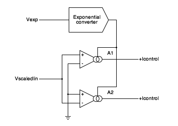
Here is a block diagram of the circuit I use to
generate +Icontrol and -Icontrol:
Block diagram of the circuit to generate the control currents
from an exponential control voltage and a scaled linear control
voltage.
|
A1 and A2 are Operational Transconductance
Amplifiers (OTA's). An OTA is an opamp-like device whose output
is a current source with a current propotianal to the differential
input voltage. The OTA gain is a transconductance, and is
proportional to the bias input current. An exponential
control voltage input, Vexp, drives an exponential converter
which provides the bias currents for the two OTAs.
Of course you can have both scaled linear and offset linear inputs:

And of course this would lead to a discussion about the most
appropriate value of Klin, which would lead to making it
voltage controlled over a wide range. Which is effectively the
same as a pair of scaled linear controls in parallel. And it is
completely practical to parallel multiples of the above circuit.
Voltage Controlled Phase Shift
The quadrature trapezoid core also enables the implementation of
voltage controlled phase shift over a multiple cycle range. I'll
cover the details of this in a later article.
While the Yamaha DX7 synthesizer is well known for its use of FM
Synthesis, it really works with phase modulation. (The phrase FM
Synthesis is used as a generic term to describe both frequency and
phase modulation.) So analog versions of many DX-7 algorithms
are good applications for voltage controlled phase shift.
Summary
This article is an introduction to the quadrature trapezoid VCO
describing the basic operations and features and suggesting some
possibilities. Future articles will explore this more.
References
ASM-1 Analog Synthesizer Module,
Gene Stop and Magnus Danielson.
Moog Modular System Technical Service Manual,
Norlin Music.
ARP 2600 Service Manual,
ARP Instruments, Inc., September 1977.
The Synthesis of Complex Audio Spectra by Means of Frequency
Modulation,
John M. Chowning, Journal of the Audio Engineering Society, 1973.
US Patent 4,018,121: Method of Synthesizing a Musical Sound,
John M. Chowning, Issued April 19, 1977
US Patent 4,554,857: Electronic Musical Instrument Capable of
Varying a Tone Synthesis Operation Algorithm,
Tetsuo Nishimoto, November 26, 1985
Bucha 258B Oscillator Module Schematic,
Don Buchla, June 1970.
CA3280 Dual Operational Transconductance Amplifier,
Intersil data sheet.
Updates
19 July 2003 Originally published.
24 July 2003 Spelling, typos, tweaks.


